
Process Selection
Should this part be laser cut or press brake formed?
Laser cut vs press brake formed: when a flat laser-cut part (tab-and-slot, weldment, bolt-up) beats a bent one on cost, tolerance, and lead time — and when the bend is the right call.
By Nevatronix Laser 8 min read
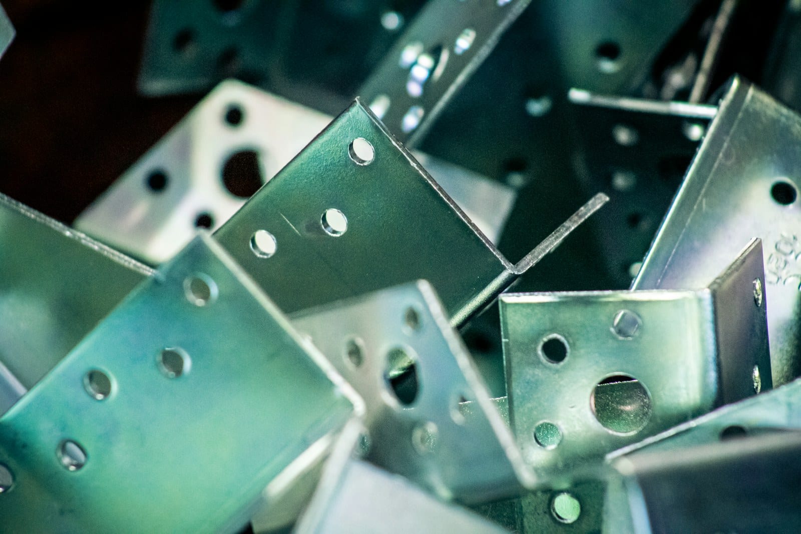
Laser cutting and press brake forming are the two operations that make most sheet metal brackets and chassis: the laser cuts a flat profile, the brake folds it. The question is whether to bend the part or build it from flat laser-cut pieces. Bend simple one-gauge profiles; laser cut and join parts that need tight feature positions, mixed thicknesses, or corners a brake cannot reach.
What’s the actual difference?
Press brake forming takes a laser-cut flat blank and bends it between a punch and a V-die into an L, U, Z, hat, or box. The part stays one piece, one thickness, one material. The fold is a structural feature in its own right: a 90° flange stiffens the panel more than the same mass of flat sheet ever could. Every flange costs a brake setup and a bend cycle, and every dimension across a bend inherits the bend’s angle and position tolerance.
A laser-cut flat design avoids the bend entirely. The geometry that would have been a flange becomes a second flat part, located to the first by tab-and-slot features, a weld, or bolts. Nothing is formed, so nothing springs back and no feature is stretched near a bend line. The cost moves to the joint: a weld pass, a fastener, or a tab that has to be cut on both mating pieces.
We run both processes under one roof. Nevatronix Laser cuts the blanks on a 3 kW fiber cell (see flat sheet laser cutting); the co-located Nevatronix Sheet Metal line forms them on press brakes to 200 tons and 4000 mm (see press brake forming). We have no reason to steer you toward either. This article is how we decide when a print arrives with the choice still open.
Laser cut vs press brake formed at a glance
| Decision factor | Press brake formed | Laser cut flat, then joined |
|---|---|---|
| Part count | One piece | Two or more pieces plus a joint |
| Thickness | One gauge throughout | Each piece can be a different gauge or alloy |
| Feature position tolerance | About ±0.13 mm (±0.005 in) across a bend | ±0.05 mm (±0.002 in) feature-to-feature on the flat |
| Angle | ±0.5° bend angle | Set by the joint: tab-and-slot self-squares, bolt-up is fixture-dependent |
| Stiffness per gram | High — the fold is a stiffener | Depends on the joint; welded corners are stiff, bolted ones less so |
| Cosmetic corners | Clean radius, no visible joint | Weld or fastener visible unless dressed |
| Setup per part | Brake setup plus a cycle per bend | None beyond the nest; joint labor per assembly |
| Design change cost | New flat pattern and bend program | New DXF only |
| Sweet spot | Single-gauge boxes, brackets, panels | Mixed-gauge structures, precision plates, low-volume weldments |
Most brackets sort themselves on the first three rows: if the part is one gauge and its critical dimensions are not across a bend, form it.
How does tolerance stack across a bend?
This is the row that decides precision parts. On the flat, a laser holds hole positions to ±0.05 mm (±0.002 in) with ±0.025 mm repeatability, and the edge lands in ISO 9013 range 2. That accuracy survives forming only for features that stay on the same face as their datum.
Once a dimension crosses a bend line, three more terms enter the stack: the bend angle (±0.5° on production runs), the bend position along the blank, and the bend deduction the flat pattern assumed for that material lot. A 0.5° angle error on a 100 mm flange moves the flange tip by about 0.9 mm. The formed-part tolerance we quote on sheet metal work is ±0.13 mm (±0.005 in) for exactly this reason, and it widens with flange length. The sheet metal tolerance reference on the sibling site works through the arithmetic; the practical rule is short:
- Feature to feature on one face: laser-cut tolerance applies. Design here whenever you can.
- Feature to a bend, or across a bend: formed tolerance applies. Put the loose dimension here.
- Feature to feature across two bends (hole in each side wall of a U): the stack doubles. If that dimension is critical, cut the side walls flat and locate them to the base with tabs and slots instead.
A tab-and-slot assembly does not escape tolerance; it converts it. The angle is set by the slot geometry and the tab, both laser cut, so the assembly squares itself within the cut tolerance before any weld fixture is involved.
When does the part need more than one thickness?
A press brake bends whatever gauge the blank is, everywhere. That is fine for an enclosure lid and a problem for a bracket that needs a 6 mm mounting foot and a 1.5 mm cover flange. The usual fix — form the whole part at 6 mm — spends material and weight on flanges that carry nothing.
Laser-cut construction has no such rule. A 6 mm foot, a 3 mm gusset, and a 1.5 mm shield are three flat parts from three nests, each in the right material, joined at the corner. Mixed materials work the same way: a stainless face on a mild steel frame, or a copper bus tab on a steel bracket, is a joint in a cut design and impossible as a single formed part.
The same logic covers thickness the brake cannot form at all. Our brake line forms mild steel to 8 mm and aluminum to 10 mm at full length; the laser cuts mild steel to 12 mm. A 10 or 12 mm mild steel plate part is a cut-and-weld part by default. For how the cell behaves at those gauges, see how thick a 3 kW fiber laser actually cuts.
What does geometry rule out for each process?
A press brake needs room. The punch has to enter and the flange has to clear the die. As typical industry guidelines, not our quote: the minimum flange is roughly four times material thickness plus the bend radius (our brake line’s floor is 5 mm), a hole should sit at least 2 to 2.5 times thickness plus the inside radius from the bend line or it ovals, and each successive flange must not collide with tooling or with a flange already formed. Closed boxes with four return flanges, deep narrow channels, and inward-facing flanges inside a small opening are where forming runs out of reach. The bend radius chart on the sibling site covers the radius side of that.
A laser needs a joint plan. Flat construction cannot make a continuous radiused corner, a sealed fold, or a hem. Every corner is a joint, and each joint is either a weld (heat, distortion on thin gauge, a bead to dress if cosmetic), a fastener (hardware cost, assembly time, a hole pattern to tolerance), or a tab in a slot (self-locating, but the tab shows on the outside face unless it is recessed). For a leak-tight seam or a class-A radius, the bend wins outright.
Where the geometry is honestly in the middle — a bracket with one awkward flange — the answer is often a hybrid: form the easy flanges, laser cut the awkward one as a separate piece, and tab it in.
What does each route cost at your volume?
Per operation, the flat part is cheaper. It has no brake setup, no bend cycle, and no springback tuning on the first article. The trade is the joint, and joints are labor.
For a one-gauge bracket, a single formed part is nearly always the cheaper finished piece. One blank, one setup, two or three bend cycles, no welding, no hardware. Adding a second cut plate plus a weld to avoid a bend that the brake handles easily is a net loss at any quantity.
For a mixed-gauge or precision assembly, the arithmetic reverses. Forming means a thicker blank than most of the part needs, a longer setup for the awkward flange, and a tolerance you then have to fixture or ream back to spec. Cutting and joining means a few extra parts from nests that were running anyway, plus a tab-and-slot weld our robotic cells fixture themselves.
Volume tilts it further. At 1 to 50 pieces, forming setup is a visible share of the price; a tabbed weldment spreads no setup at all. At 5,000 pieces, a one-hit bend amortizes to almost nothing per part, while a weld stays a weld on every unit. Design changes follow the same pattern: a laser-only part changes with a new DXF; a formed part also needs a new flat pattern and bend program, and sometimes a first-article re-check for springback.
When press brake forming still wins
Form the part when:
- It is one gauge and a simple profile. L, U, Z, hat, and box pans are what a press brake exists for. One part, no joints, no heat.
- The fold is the structure. A formed flange stiffens a panel more efficiently than any welded strip. Chassis and enclosure walls should be folded, not fabricated.
- Corners must be sealed or cosmetic. A bent radius is continuous; a welded corner needs a bead, dressing, and often filler. Powder-coated enclosures and visible kiosk panels are formed parts.
- Volume is high. At thousands of units, a bend cycle is cheaper than any joint you can design.
- Thin gauge. Below about 1.5 mm, welding distorts and tabs are fragile; the brake handles thin material without either problem.
In those cases we cut the blank and send it across the floor to the brake. A laser-only design would cost you more and arrive with a joint you did not need.
When laser-cut flat construction wins (precision and mixed-gauge parts)
Cut it flat and join it when:
- Feature positions are tight across what would be a bend. Two holes on opposite side walls that must align within ±0.1 mm are a tab-and-slot part, not a U-bend.
- The part needs more than one thickness or material. A thick foot, a thin cover, a stainless face on a steel frame.
- The geometry is out of the brake’s reach. Closed boxes, deep narrow channels, inward flanges, flanges under 5 mm.
- Material is thicker than 8 mm mild steel or 10 mm aluminum. Plate parts are cut-and-weld parts.
- Volume is low and the design is still moving. A tabbed weldment changes with a DXF and carries no setup.
- You want a self-fixturing weldment. Tabs and slots square the assembly before the first tack; the same technique works on tube frames from our tube laser.
For everything else, and that is most brackets, bend it.
How we’d quote your part
Send a STEP with material, thickness, quantity, and which dimensions are critical, and we will tell you whether it forms cleanly or wants to be cut and joined. Both routes run in the same building, so the quote covers the whole part either way. Start at our quote page.
References
- ASTM A1008/A1008M — Standard specification for steel sheet, cold-rolled, carbon, structural, and high-strength low-alloy
- ASME Y14.5 — Dimensioning and tolerancing
- ISO 9013:2017 — Thermal cutting: classification of thermal cuts and edge quality
- AWS standards catalog — structural welding codes (D1.1 steel, D1.2 aluminum)
- NIST — dimensional metrology and manufacturing measurement resources
Frequently asked questions
- Should I laser cut or bend this bracket?
- Bend it if the bracket is a simple L, U, or Z profile in one gauge: one press brake setup gives you a single part with no joints, and the fold itself adds stiffness. Laser cut it flat if the bracket carries tight feature-to-feature positions, needs different thicknesses, or is really a small assembly — tab-and-slot or bolt-up construction holds ±0.05 mm feature position where a formed flange holds about ±0.13 mm.
- Is laser cutting cheaper than press brake forming?
- Per operation, a laser-cut flat part is cheaper because it skips the brake setup and bend cycle. Per finished part, that only holds if the flat pieces do not need welding or bolting to replace the bend. A single formed bracket is usually cheaper than two laser-cut plates plus a weld; a multi-thickness assembly is usually cheaper cut and joined than forced through the brake.
- How does tolerance compare between a laser-cut feature and a formed flange?
- A laser-cut hole or edge lands within about ±0.05 mm (±0.002 in) of its nominal position on our flat sheet cell. A feature on a formed flange stacks the cut tolerance with bend angle (±0.5°) and bend position, which typically opens it to about ±0.13 mm (±0.005 in) or more, growing with flange length. Put the critical feature on the flat, or on the same flange as its mate.
- What is tab-and-slot construction and when should I use it?
- Tab-and-slot cuts locating tabs on one flat part and matching slots on another so the pieces self-locate at 90° before welding. It replaces a bend where the part needs a thicker wall, a different material on one face, or a corner that a press brake cannot reach. It costs a weld or a fastener per joint but no forming setup, so it suits low volumes and mixed-thickness structures.
- Can you laser cut a part and bend it at the same shop?
- Yes. Nevatronix Laser cuts the flat blank, and the co-located Nevatronix Sheet Metal press brake line forms it — up to 4000 mm bend length at 200 tons, with a 5 mm minimum flange. One PO covers both, the blank never leaves the building, and the bend relief, hole-to-bend distances, and flat pattern are checked once, together.
- When does a formed part beat a welded flat assembly?
- When the geometry is a thin-wall box or profile in one gauge, when cosmetic surfaces cannot show a weld, when the part must be sealed or leak-free at the corner, or when volume is high enough that a one-hit bend is cheaper than a joint. A fold is also stiffer per gram than a welded corner and carries no heat distortion.
- How close to a bend can a laser-cut hole be?
- As a typical industry guideline, keep the hole edge at least 2 to 2.5 times material thickness plus the inside bend radius away from the bend line, or the hole will stretch into an oval as the flange forms. If the hole must sit closer than that, add a bend relief, move the hole, or split the part into a cut-and-joined design; a flat sheet laser cannot cut the hole after forming.