
Flat Sheet Capability
ISO 9013 range 2 in practice: what edge quality you actually get
What ISO 9013 range 2 means on a laser-cut edge: perpendicularity (u) and mean height of profile (Rz5) limits, how thickness shifts them, what range 2 looks like on 1, 3, 6, and 12 mm.
By Nevatronix Laser 8 min read
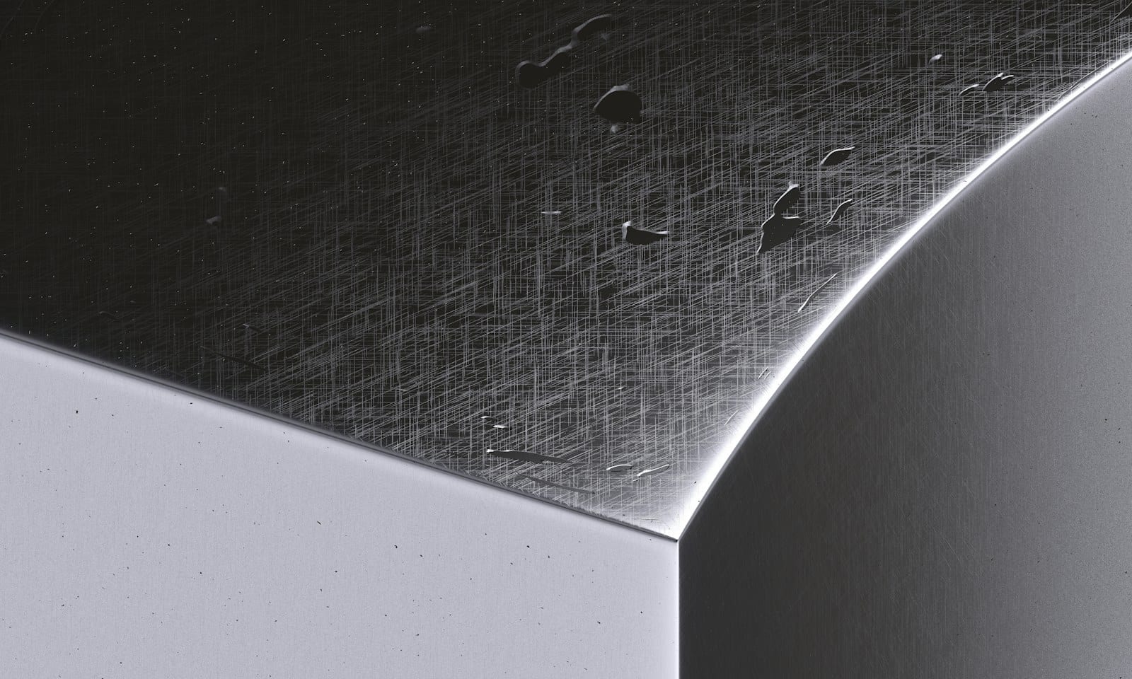
ISO 9013 is the international standard that classifies the quality of thermal-cut edges, including laser cuts, by two measurements: perpendicularity or angularity tolerance (u) and mean height of profile (Rz5). Each has numbered ranges, range 1 tightest, with limits that widen with material thickness. Range 2 is the production edge on our 3 kW flat sheet cell: square to about 0.2 mm and 40–50 µm Rz5 through 12 mm.
What does ISO 9013 actually measure?
The standard applies to oxyfuel, plasma, and laser cutting, and grades the cut face on geometry, not chemistry. Two quantities carry numbered ranges.
Perpendicularity or angularity tolerance, u. Picture the cut face in cross-section. Two parallel lines are fitted at the nominal angle (90° for a square cut, or the bevel angle for a beveled one) so they enclose the whole profile, and the distance between them is u. It captures taper, where the kerf is wider at the top than the bottom, and any lean of the face. The measurement deliberately excludes a narrow band at the top and bottom of the edge where melting and dross distort the profile, so u describes the usable face, not the burr.
Mean height of profile, Rz5. This is the roughness of the cut face measured along the cut direction, at a defined depth below the top edge. Five consecutive sampling lengths are measured, the peak-to-valley height of each is taken, and the five are averaged. On a laser edge Rz5 is dominated by the fine vertical striations the melt front leaves as it moves through the sheet.
Other characteristics of the edge are described in the standard but not ranged: drag (the lag of the striations behind the beam), top-edge melting, and dross adhesion. The standard does not address oxide, color, or edge hardness at all, which is why an ISO 9013 range on a drawing should sit next to an edge-condition note rather than replace one.
How do the ranges scale with thickness?
Every range limit in ISO 9013 is a base value plus a term proportional to thickness a in millimeters. The limits below are the standard’s range formulas as applied on our cell for laser cutting, rounded to the precision a shop measures at; the standard itself is the controlling document and a drawing should reference it, not this table.
| Thickness | u, range 1 | u, range 2 | u, range 3 | Rz5, range 1 | Rz5, range 2 | Rz5, range 3 |
|---|---|---|---|---|---|---|
| 1 mm (0.04 in) | ≤ 0.05 mm | ≤ 0.16 mm | ≤ 0.41 mm | ≤ 11 µm | ≤ 41 µm | ≤ 71 µm |
| 3 mm (0.12 in) | ≤ 0.06 mm | ≤ 0.17 mm | ≤ 0.43 mm | ≤ 12 µm | ≤ 42 µm | ≤ 74 µm |
| 6 mm (0.24 in) | ≤ 0.07 mm | ≤ 0.19 mm | ≤ 0.46 mm | ≤ 14 µm | ≤ 45 µm | ≤ 77 µm |
| 12 mm (0.47 in) | ≤ 0.09 mm | ≤ 0.23 mm | ≤ 0.52 mm | ≤ 17 µm | ≤ 50 µm | ≤ 84 µm |
Two things follow. First, the range number is a thickness-independent way to say “this good,” which is why a shop can hold one range across its whole envelope while the millimeter values move. Second, the steps between ranges are large: range 3 allows roughly two and a half times the perpendicularity error of range 2 and about 1.7 times the roughness, and range 1 is tighter than range 2 by a similar factor. There is no such thing as “slightly better than range 2.” A drawing that needs more than range 2 has jumped to a different class of process control.
What does range 2 look like on 1, 3, 6, and 12 mm?
The formulas describe an envelope. What comes off the table inside that envelope varies with thickness and assist gas, and this is what a procurement engineer should expect to see.
1 mm sheet, nitrogen. The face is bright and nearly striation-free, u is a few hundredths of a millimeter, and Rz5 sits far below the range 2 limit; a thin nitrogen cut on stainless or cold-rolled steel commonly measures inside range 1 without trying. The usable band of the face is narrow, so a small burr at the bottom edge is proportionally more visible even though the standard excludes it from u.
3 mm sheet, nitrogen or oxygen. Still a bright, square face on nitrogen. On oxygen the mild steel face carries a matte oxide skin and slightly more visible striations; geometry stays comfortably in range 2. Kiosk panels, brackets, and enclosure blanks live here and rarely need any edge work.
6 mm, stainless on nitrogen or mild steel on oxygen. This is the top of our stainless envelope. The striations are visible and the lower third of the face is rougher than the top, which is normal for a fusion cut at full thickness. Perpendicularity stays inside range 2 (≤ 0.19 mm); Rz5 is measurable at 30–45 µm and worth checking on the first article rather than assuming. The nitrogen vs oxygen assist gas guide covers why the stainless edge is bright and the steel edge is not at this thickness.
12 mm mild steel, oxygen. The top of our mild steel envelope, and the thickness where range 2 is held rather than given. The face is oxidized, the striations are coarse and lag behind the beam, and the bottom edge can carry light dross that is scraped or wiped rather than ground. The face measures square within 0.23 mm and Rz5 within 50 µm when the cut is tuned; run faster than that and the edge drops to range 3. The behavior of the cut at this ceiling is the subject of how thick a 3 kW fiber laser actually cuts.
Across all four, the practical meaning of range 2 is the same: the edge welds without grinding, forms without cracking at the bend, takes powder coat without prep beyond the oxide question, and fits a clearance hole or slot without hand work. That is the whole point of the grade, and it is why the flat sheet laser cutting page states it as the default edge rather than an option.
What separates edge quality from dimensional tolerance?
ISO 9013 grades the face of the cut. It does not grade where the cut is. Position and profile tolerance — ±0.05 mm (±0.002 in) on our cell, with ±0.025 mm repeatability — are separate numbers governed by the drawing’s dimensioning under ASME Y14.5 or ISO general tolerances, not by the ISO 9013 range.
The two interact in one place: kerf taper. A range 2 edge on 12 mm can lean 0.23 mm across its thickness, so a hole measured at the top and at the bottom of the plate differs by that much. A drawing that dimensions a hole to ±0.05 mm on 12 mm plate is asking for a dimension the standard’s own edge allowance exceeds. Dimension thick-plate holes at the face that matters, or call them out as drilled or reamed after cutting.
Where this breaks down
Range 2 is a production default, not a law of physics. It comes off the table only inside the process window, and there are known ways to fall out of it.
- Cutting past the envelope. Mild steel above 12 mm, stainless above 6 mm, aluminum above 5 mm on a 3 kW source. The cut may sever, but taper and Rz5 climb into range 3 and beyond.
- Pierce and lead-in zones. The point where the beam enters the sheet is always rougher than the steady-state face. Good programming puts the pierce in scrap and the lead-in on a non-functional edge; if every edge of a part is functional, say so, and the shop will lead in from a tab.
- Very small features. Holes near the 1 mm minimum and sharp inside corners force the head to decelerate, and the melt behaves differently. Perpendicularity on a 1 mm hole in 1 mm sheet is not the same as on a straight edge.
- Reflective and thick non-ferrous stock. Copper above 2 mm and brass above 3 mm are where our cell stops for a reason; the edge degrades before the beam does.
- Coated and mill-scaled surfaces. Heavy mill scale on hot-rolled plate and thick zinc on galvanized sheet can disturb the melt at the top edge and add local dross without affecting the range of the face as a whole.
- Measurement itself. Rz5 needs a stylus or optical profilometer with a defined cutoff; a fingernail test is not a measurement. If range matters enough to be on the drawing, it should be on the first-article report, and we measure it.
What to put on the drawing or RFQ
Most drawings need one of three notes, and the third is the one we see most often written when the first would do.
Nothing beyond the dimensional tolerance. For brackets, enclosures, weldment blanks, and anything with a clearance hole and a coating, the default range 2 edge is sufficient. Adding an ISO 9013 callout costs nothing but adds nothing either.
“Cut edges per ISO 9013, range 2, plus an edge-condition note.” For parts where the edge is welded, visible, or forms a fit, state the range and say what the edge has to do next: “oxide-free, weld-ready,” “dross-free, no burr on side A,” or “suitable for powder coat without secondary prep.” The range governs geometry; the note governs chemistry and burr, which the range does not.
“Cut edges per ISO 9013, range 1, on edges marked.” Reserve this for edges that are functional surfaces: a locating edge, a sealing face, a sliding fit, a visible edge on a precision cosmetic part. Mark which edges, because holding range 1 on every edge of a part slows the cut, limits thickness, and adds inspection that the unmarked edges do not need. If the drawing shows range 1 with no edge marked, we will ask.
And if the edge is welded or hidden and the part is thick mild steel, write “range 3 acceptable.” It lets the shop run oxygen faster and quote lower, and it is the one place a looser ISO 9013 range saves real money.
How we’d quote your part
Send a DXF or STEP with material, thickness, and any edge callouts, and we will quote it at range 2 by default and flag any edge that needs range 1 or can take range 3. Edge measurements go on the first-article report on request. Start at our quote page.
References
- ISO 9013:2017 — Thermal cutting: classification of thermal cuts, geometrical product specification and quality tolerances
- ASME Y14.5 — Dimensioning and tolerancing
- ASTM A240/A240M — Standard specification for chromium and chromium-nickel stainless steel plate, sheet, and strip
- AWS standards catalog — thermal cutting and weld joint preparation
- NIST — surface texture and dimensional metrology resources
Frequently asked questions
- What does ISO 9013 range 2 mean for laser-cut edges?
- ISO 9013 grades thermal-cut edges on two measured quantities: perpendicularity or angularity tolerance (u), how far the cut face leans from square, and mean height of profile (Rz5), the roughness of the cut face. Each has numbered ranges whose limits grow with thickness; range 1 is tightest. Range 2 on a laser edge means the face is within roughly 0.15–0.25 mm of square through 12 mm and its roughness is around 40–50 µm Rz5 — an edge that welds, forms, and coats without secondary finishing.
- How is perpendicularity (u) measured under ISO 9013?
- Two parallel lines are fitted to the cut face profile at the intended angle (90° for a square cut), excluding a zone at the top and bottom of the edge where melting and dross distort the profile. The distance between those lines is u. Its range 2 limit scales with thickness, starting near 0.15 mm on thin sheet and reaching about 0.23 mm at 12 mm.
- What is Rz5 on a laser-cut edge?
- Rz5 is the mean height of profile: the average of the peak-to-valley heights measured over five consecutive sampling lengths along the cut face, expressed in micrometers. On a laser edge it captures the fine vertical striations the cut leaves. Range 2 allows roughly 40–50 µm Rz5 across sheet thicknesses; a bright nitrogen cut on thin stainless typically lands well inside that.
- Does the ISO 9013 range change with material thickness?
- The range number stays the same but its numeric limit widens. Every range limit in ISO 9013 is a base value plus a term proportional to thickness, so range 2 on 1 mm sheet allows about 0.16 mm of perpendicularity error and on 12 mm about 0.23 mm. That is why a shop can state one range across its whole envelope: the standard already accounts for thicker material cutting less square.
- When should I specify ISO 9013 range 1 instead of range 2?
- Only when the edge itself is a functional surface: a sliding fit, a sealing face, a gauge-like locating edge, or a visible edge on a precision cosmetic part. Range 1 halves the allowed roughness and cuts the perpendicularity limit by two-thirds, and holding it usually means slower cuts, thinner material, and 100% edge inspection. For most parts range 2 is already tighter than the downstream process can use.
- Can I accept ISO 9013 range 3 to save money?
- Yes, on parts where the edge is welded, hidden, or ground anyway. Range 3 allows about 0.4–0.5 mm of perpendicularity error and 70–85 µm Rz5 across sheet thicknesses, which is still a usable weldment edge. It lets the shop run thick mild steel faster on oxygen and pushes a 3 kW laser closer to its top thickness. Say so on the drawing; a shop that holds range 2 by default will not loosen it unasked.
- Does ISO 9013 cover dross, oxide, or edge hardness?
- Only partly. The standard classifies perpendicularity and roughness, and describes other edge characteristics such as drag lines, top-edge melting, and dross without putting them into numbered ranges. It says nothing about oxide layer, edge color, or hardness. Specify those separately: an edge-condition note (oxide-free, weld-ready, dross-free) sits alongside the ISO 9013 range, not inside it.